SI-Light System
Project link: http://sourceforge.net/projects/si-light/
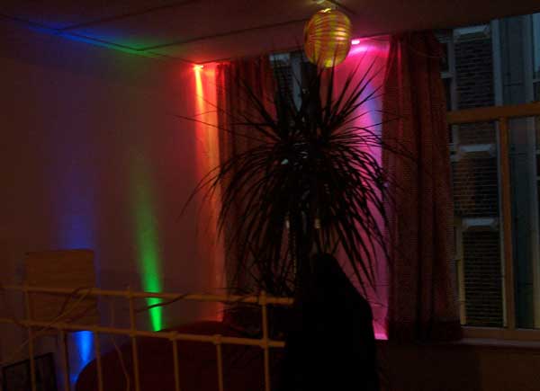
SI-Light is a experimental computer controlled home lighting system. It started with the goal of individually addressable RGB light modules that could be used to tie-dye or acid-warp my studio apartment. It is a combination of hardware, firmware, and software that was written over a few days in the summer of 2005, though it took considerably more time to etch, assemble, and install the PCBs.
The system is based on chips I used in various professional projects, such as the mighty PIC 16f628(a), and the killer TLC5940 16 channel PWM chip. Soft/firmware is written in basic - everything is pretty high level and I didn't want to mess with C for a weekend project.
THIS IS PROBABLY NOT SAFE, and no warranty is implied. The project is pretty poorly documented at this point and additional documentation will be slow coming – though I will try to get some better pictures soon. This package is released under the GPL 'as is' for all those who have written me requesting various parts.
This is NOT a commercial system: it would have to speak DMX, the professional lighting system standard.
Also: the PIC Usart is stretched to the limit in even my tiny apartment with short cable runs.
Firmware is written in mikroBasic – mikroelectronica has free compilers (to 2K).
Circuit boards are designed in EagleCAD – free for small boards.
PC control is written in VB.
Project link: http://sourceforge.net/projects/si-light/
Components
I. Development board
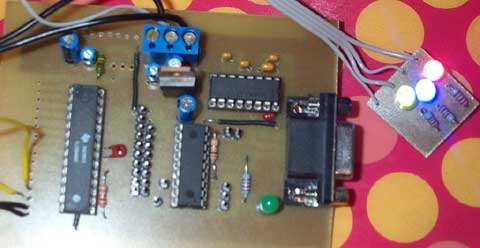
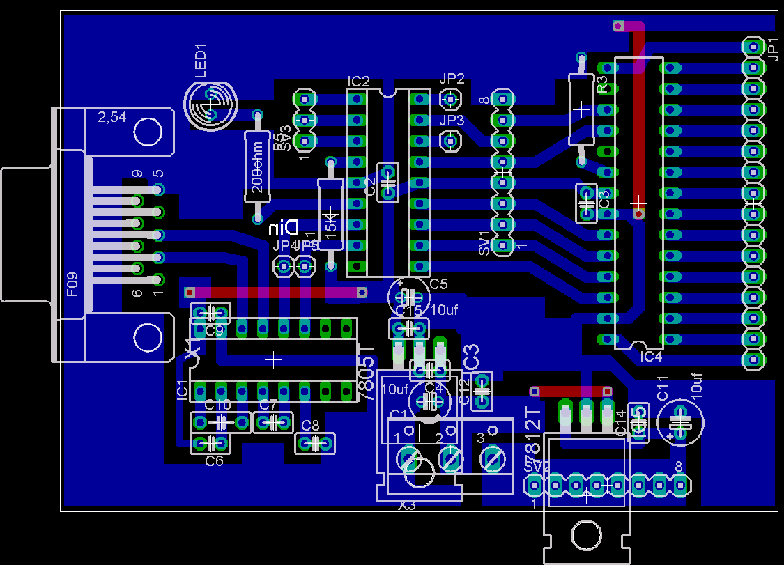
The first board I made for this project was a 'development board'. This is a single piece interface between a PC and a TLC5940 PWM. A MAX202 converts RS232 level serial input to 5v levels for a PIC 16F628(a) microcontroller. The PIC receives various commands through it's uart and clocks data into the TLC5940. This board was used for firmware development, but might be useful for experimentation or to drive a few RGB pods (up to 5) from a PC. This is the last PCB I ever made using the toner transfer method.
1. RGB light pods
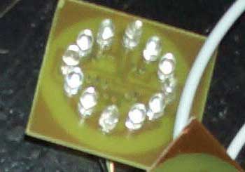
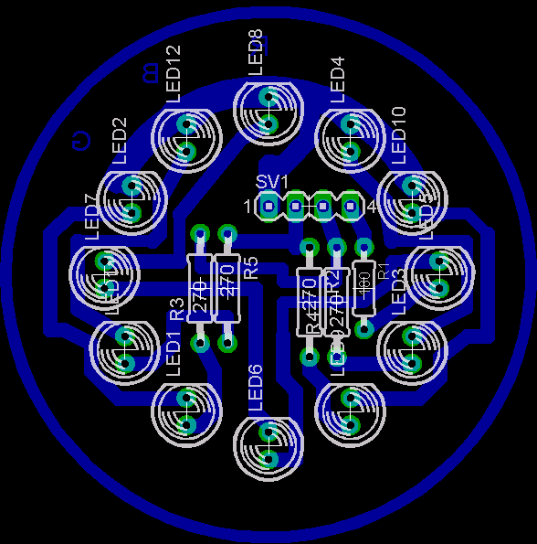
The RGB light 'pod' is based on a design by Big Clive at http://www.bigclive.com. The design was modified, primarily to have fatter traces and better clearance in some areas. Each pod consists of 4 each red, green, and blue LEDs. The pods are designed for 12 volts, and use 100ma at full brightness (2 series of 2 and one series of 4 = 5*20mA=100mA@12V). I used cheap, high powered, Chinese LEDs that work better than I ever imagined. These things are seriously bright – giving a significant color wash even in high ambient light conditions. Remember that the TLC5940 sinks current from the cathode, thus +12V is supplied to the module through anodes at the 'top'. All LED anodes should be oriented towards the top.
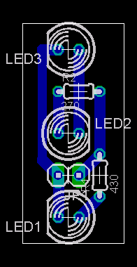
There is also a small PCB for 3 white bulbs included.
2. PWM modules
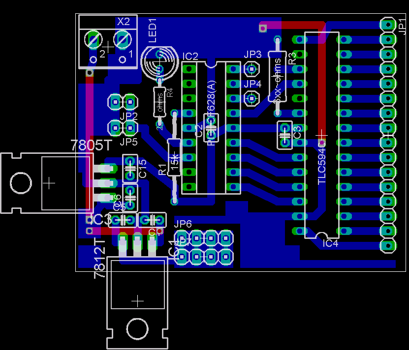
PWM modules drive up to 5 light pods each from the 16 PWM channels of the TLC5940. Modules are an upgraded version of the development board, without the MAX202, but with a 12V supply for the LEDS. A small LED on the PWM module blinks when a command is executed.
A. Design
Multiple PWM modules are tied together in a crude network through the uart of the PIC16F628(a). The network is driven by a PC (through a MAX202) or a custom control box of some sort (see below). This type of network has serious limitations, but works great for my small apartment.
The system works something like this:
1)Instructions are sent through a serial port (PC or microcontroller) to all PWM modules attached to the system.
2)The PIC16F628(a) on each PWM module receives the message packet through the hardware uart.
3)The PIC evaluates the packet to determine if it is A) addressed to it, or B) a global packet. If it is nether the PIC returns to waiting for new instructions.
4)If the packet is relevant, the PIC inserts values from the packet into a 16 byte array representing the 16 PWM channels on the TLC5940. (See packet format documentation below)
5)The PIC then goes into a subroutine that clocks the byte array into the TLC5940.
The TLC5940 PWM needs a clock with a reset every 4096 ticks. This is accomplished by using the clock out from the PIC's internal oscillator (4Mhz). Timer0 (configured with an appropriate prescaler) provides the reset on interrupt.
B. Control Protocol
PWM modules are controlled through a simple serial protocol. The length of the command string is ALWAYS the first byte. Default serial configuration is 19200bps, 8,n,1.
COMMAND TABLE
*The address is a unique number between 0 and 254 programmed into EEPROM byte 00 of each module, see firmware below. +The 16 bytes of data represent TLC5940 PWM channels 0-15, in order.
|
Length |
Address* |
Command |
Data/Values |
Description |
|---|---|---|---|---|
|
18 |
0...254 |
0
|
16 bytes, 0-255+ |
Set the duty cycle for each channel of the TLC5940 . |
|
18 |
0...254 |
1 or 2
|
16 bytes, 0-255+ |
Set the duty cycle for each channel on a second or third TLC5940 in cascade configuration... never used, thus unfinished. |
|
3 |
0...254 |
255 |
1 byte, 0-254 |
Program a new module address. |
|
3 |
0...254 |
254 |
1 byte, 0-2 |
Program a new number of cascaded TLC5940s. (Never used/finished) |
|
18 |
0...254 |
253 |
16 bytes+, 0-2 0=Red 1=Green 2=Blue |
Program location of R/G/B lights. This enables global value setting. |
|
2 |
255 (Global address/packet to all) |
0 |
NONE |
Disable interrupts, thus power down the TLC5940 |
|
2 |
255 (Global address/packet to all) |
1 |
NONE |
Enable interrupts after a disable (enabled by default) |
|
3 |
255 (Global address/packet to all) |
2 |
1 byte, 0-255 |
Set all PWM channels to value. |
|
5 |
255 (Global address/packet to all) |
3 |
3 bytes, 0-255 byte1=RED val byte2=GREEN val byte3=BLUE val |
Set R/G/B channels to value. |
C. Using the firmware
Two versions of compiled firmware are included in the package, one each for PIC16f628 & 16f628A. I run both of these in my system without problems.
The EEPROM is used to hold module address (location 00), number of cascaded TLC5490s (location 01), and the R/G/B channel assignments (location 3-18). ONLY THE ADDRESS AND NUMBER OF TLC CHIPS IS REQUIRED TO INITIALIZE THE MODULE. These two bytes MUST be written when you program the firmware, or the module will not startup correctly. The R/G/B channel information can be written with the firmware (if known), or can be programmed later through the network. Remember – the cascaded TLC function was never used, and probably doesn't work. It should be deprecated from the firmware in a future release – a value of 1 should be written if you are using the designs included in the package.
FUSES: LVP should be disabled, internal oscillator enabled with clock out, WDT off. Other functions as you see fit.
If you don't have a PIC programmer, there is a design and PCB included in the package to build the simple uJDM programmer. It is designed to be toner transfer friendly and uses, like, 6 parts. I've programmed 100s of PIC 16f84(a) and 16f628(a)'s without problem using this design.
3. PC interface
This little (and really messy) VB application issues commands to the PWM modules through the PC serial port. Serial port output should be taken to 5v logic level through a MAX202, such as the host board design in the package.
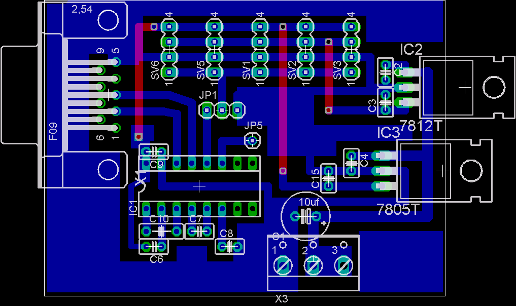
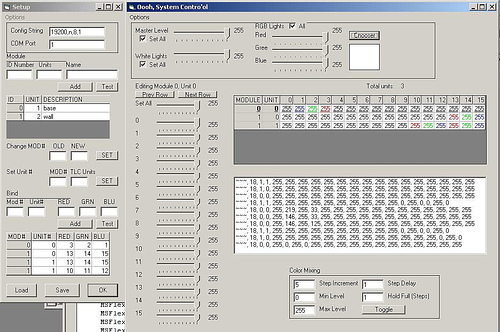
Terrifically undocumented and slightly clunky, this is the basic operation of the program:
A) Configurations can be saved and loaded from .ini files, the default configuration file is config.ini. To start a new configuration you really have to open config.ini with a text editor, clear its contents, and save.
B)To add a PWM module to the system, enter the address programmed in the EEPROM in the ID Number box, the number of cascaded TLC5940 chips (usually 1), and a description of the module. Click 'ADD'.
C)To tell the program which PWM channels are clustered into RGB pods, enter the address (Mod #), TLC5940 number (starting with 0, eg for 1 TLC chip, the Unit# is 0), and the PWM channels for R/G/B (0-15). Click 'ADD'. Repeat as needed.
D) When finished with configuration, click 'save'.
E) Click 'OK' to populate the control grid with a visual representation of the configuration.
The system control has various features/functions:
A) Click on a module number to edit the PWM settings using the slider to the left.
B) Click on any red, green, or blue cell to display the windows color picker. Choose a color. The R/G/B values will be set to the specified color.
C) Master controls at the top allow global color selection and dimming.
D) A really bad color fade implementation is enabled with the toggle button.
E) The center window echos serial commands sent to the serial port to help with debugging.
A second program, 'System tools', issues the global configuration commands listed in the command chart above.
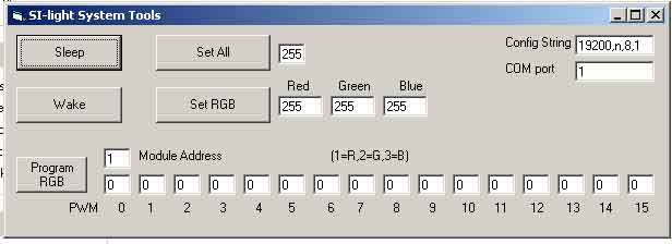
4. Control Box
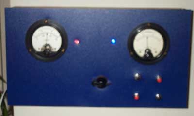
The control box was designed as an alternate to PC control. It uses a PIC16f628(a) to issue commands to the PWM modules without the use of a desktop computer. The main criteria for this design was 'big analog bits', and it delivers. It is based on a hand-made voltage/current meter I bought at the Waterloomarkt for 2 euros. I recycled the nice analog gages, box, and switches, but replaced the face and inserted new guts. The analog gages show an average of the R/G/B values broadcast to the PWM modules. They are controlled from the hardware PWM of the PIC. The LEDs show power and network activity. The LEDs here have been sanded flat for a more diffused light. The small buttons control dimming and system power. The centerpiece of this salvage-based design is the bakelite rotary switch which makes a most pleasing 'thump' as it turns. It selects a steady color of R-O-Y-G-B-I-V, or one of two fade programs: circular color fade or random color fade.
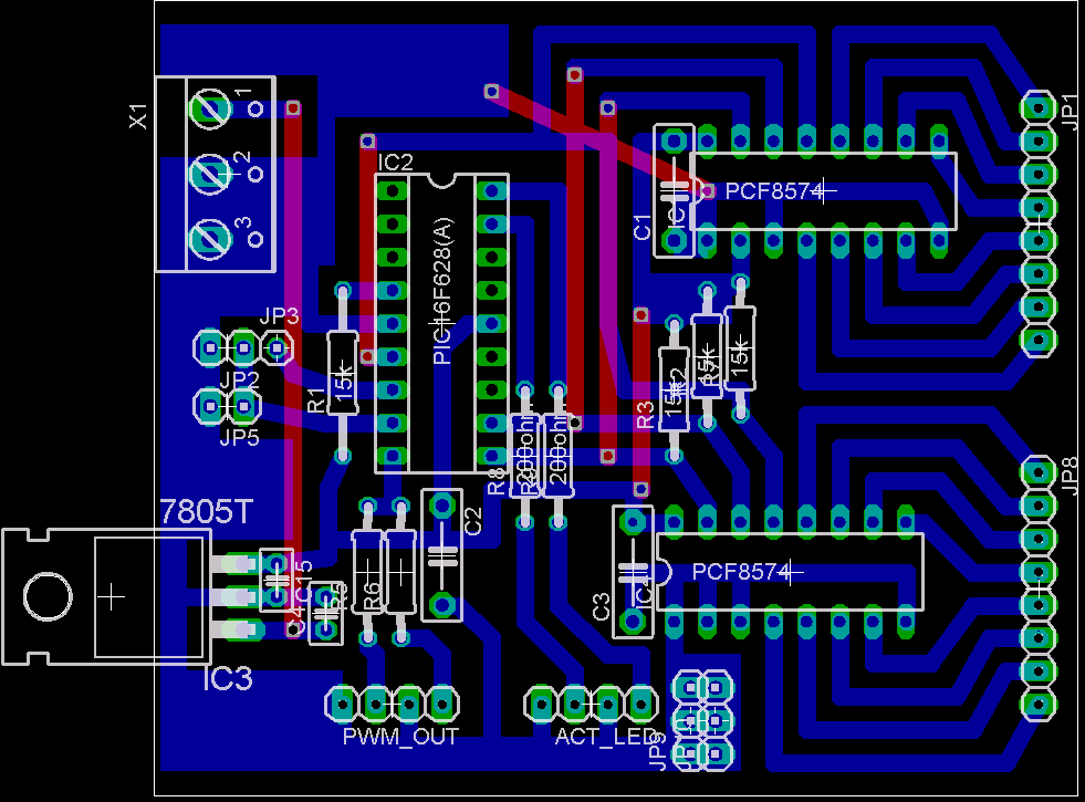
The PCB and firmware for the control box are included in the package. I used parts that I had around (like the PF8574 I2C I/O chip), anyone using this design would probably want to tailor the PCB&firmware to their own needs. Notice that the firmware skips a pin on I/O expander 1, this is because one I/O on my I/O chip was faulty.
Project link: http://sourceforge.net/projects/si-light/
Contact: Silight-at-whereisian.com